Aladon’s Root Cause Failure Analysis (RCFA) methodology is a continuous improvement tool for your organizational asset strategy, and when used together with other reliability processes such as RCM and RBI, provides a holistic approach to asset failure management.
The following case study of a blower fire in a food manufacturing plant shows how Aladon uses RCFA to get to the root cause of a physical asset problem and support a reliability culture.
A case study in RCFA
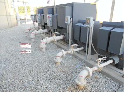
In November 2016, Blower B at a food production plant caught fire in the late morning. The fire spread to nearby blowers A and C due to their proximity to blower B. Fortunately no one was injured, and an on-duty operator, who first noticed the fire, was able to extinguish it with the help of others before any severe damage occurred.
To determine the cause of the fire, an Aladon Network Member conducted a Root Cause Failure Analysis (RCFA) at the plant.
Aladon’s Root Cause Failure Analysis (RCFA) methodology is a continuous improvement tool for your organizational asset strategy, and when used together with other reliability processes such as RCM and RBI, provides a holistic approach to asset failure management.
Whereas RCM is applied proactively (before the failure occurs) and delivers the best proactive failure management strategy for all types of assets (Operating Contexts), RCFA is applied reactively (after the failure has happened) to allow reliability engineers the ability to maximize equipment availability and improve asset performance.
The primary function of the blowers that caught fire at the plant is to supply air to the aeration basin. The blowers are slaved to a Dissolved Oxygen (DO) meter installed in the aeration basin, and a blower starts whenever the DO drops to a certain level. If the DO continues to be below the desired DO level programmed into the PLC, a second blower will start. In rare cases, such as plant upset, all three blowers will operate at the same time.
The manufacture recommendation for the blowers’ spacing is 28 inches. However, these blowers that caught fire only had 16 inches of clearance between each unit.
Using RCFA to determine what went wrong
Based on observations and interviews, the root cause of the failure was a “single-phase event” that occurred sometime early on November 5.
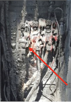
Over time, the loose or corroded connection heated up to the point that it separated from the circuit. This caused phases “B” and “C” to carry extra current and then the motor heated up significantly and vibrated vigorously. The heat was generated at the disconnect, not the blower, because of the melting pattern on the flex conduit.
Once blower B was engulfed in flames, the remaining two blowers experienced a dramatic increase in inlet temperature. The elevated inlet temperature to the blowers most likely caught the filter on fire and then spread to the internal sound attenuation insulation and then oil vapors.
On duty responders report on what they saw for RCFA analysis
An Aladon Network Member performed an RCFA analysis. At the time of the fire, the responding operator reported that the disconnect for blower B was glowing red and fire was escaping through the top of the unit. Because the disconnect switch is external to the enclosure, it could not have ignited insulation or oil vapors within the enclosure. The heat originated from the disconnect box and not the enclosure, based on observation of the conduit that leads from the disconnect to the motor.
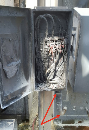
A second operator noted that after the event, the main breaker in MCC A unit in the treatment area was tripped. All the other equipment on MCC A was restarted once the breaker was reset.
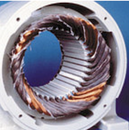
Once a motor experiences a “single phasing event,” the windings display a particular burn pattern. Blower B motor shows signs of this pattern. However, since the motor was also in an enclosure with the fire, further winding damage occurred.
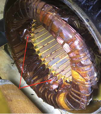
The RCFA investigating team removed the motor and disassembled it. They found that the sealed bearings and rotor were in good condition. However, the motor connection box was charred, and several motor leads were burned. The motor was wired in the wye configuration.
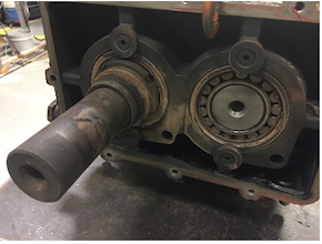
Next, the team took apart the blower for review. They found that the timing gears, rotary lobes, and bearings showed no catastrophic failure. The bearings turned by hand and did not show any sign of failure due to lack of lubrication. (Photos 5, 6, 7, and 8)
Photo 5 – Non drive end bearings
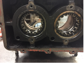
Photo – Rotary Lobes
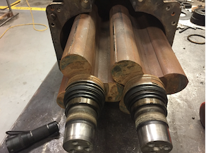
Photo 7 – Timing gears
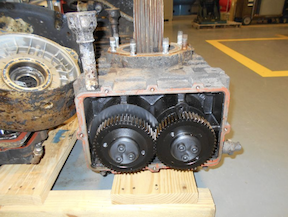
Photo 8 – Drive end bearings
It was clear that the units’ installation accounted for some of the contributing factors to the fire. The units needed to be spaced at a minimum of 28 inches, according to the O&M Manual for Kaeser. The actual installation distance even at the time of the RCFA analysis was 16 inches.
Photo 9 shows the current distance.
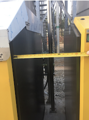
This reduced spacing allowed the heat from the fire on blower B to be directed to the other two blowers. Then, these elevated inlet temperatures caused the units to overheat and catch fire as well. The typical discharge temperatures are typically in the 230 degrees F range. The addition of heat from the blower B fire dramatically increased this temperature and affected the blowers.
Blower B Protection Devices
The Kaeser blower package comes with a local discharge air temperature gauge, and there are no devices to detect the internal temperature in the units. However, the option is available for the customer upon request.
The motor protection is provided through three 125A fuses and the Allen Bradley soft start unit. The fuses were not blown (based on MCC A main breaker tripping) on blower B, and the Allen Bradley unit did not shut down the unit. After the fire was extinguished, the MCC A main breaker was tripped.
Recommendations based on the RCFA analysis
- The Fire Marshall suggested that the units be separated further and/or installing a firewall between the blower units.
- Ensure the trip settings on the Allen Bradley soft start units are set correctly. (84.4 FLA)
- Examine the needed fuse size for the Blower MCC bucket. At the time, 125A fuses were installed. With full load amperage and 1.15 service factor, 100A fuses may be warranted.
- Examine adding an excessive temperature switch inside the enclosure.
- Remove blowers A and B with motors for use as future spares. These units can be rebuilt and placed into inventory.
Learn more about RCFA or click here to contact us to find out more about Aladon thoughtware and software for physical assets.